
to draw the flow charts and plant layouts) FLOW CHART A flow chart is a representation of sequence of operations in a processing plant or in a process. For example, if we want to prepare dried vegetables, the sequence of operations will be sorting, washing, peeling, slicing and then drying either under sun or in a mechanical dryer. But
 WhatsAppGet PriceGet A Quote
diagram for sand washing plant excellent mining crushing machinery products or production line design the company is committed to building the Chinese brand mine crushing and processing machinery mainly crusher mill sand making our products diagram for sand washing plant in more than one hundred of the worldsales of countries and regions .
WhatsAppGet PriceGet A Quote
Client: Atlantic Pumps Ltd. UKUsed in the mining industry, a wash plant helps to clean dirty sand. In this 3D animated explainer video, you can see the diff...
WhatsAppGet PriceGet A Quote
Year 7 Biology Cells Q1. Nadine mixed grass seeds with sand. She put the mixture into three mesh bags to make three model heads. She soaked two of the bags in water.
WhatsAppGet PriceGet A Quote
side, the new sand is added, and the old sand replaced on the top of the new, thus retaining much of the active material to enable the resanded filter to become operational with the minimum re-ripening. This process (of replacing old sand on the top of the new) known as “throwing over” is carried out in strips.
WhatsAppGet PriceGet A Quote
The sand processing rates at the wash plant are 400 TPH, and approximately, ,000 tons6 per day (TPD). The applicant provided a process flow diagram and an aerial map below to show the source locations.
WhatsAppGet PriceGet A Quote
storage and loading facilities. A process flow diagram for construction sand and gravel processing is presented in Figure 11.19.1-1. The following paragraphs describe the process in more detail. After being transported to the processing plant, the wet sand and gravel raw feed is stockpiled
WhatsAppGet PriceGet A Quote
26–6 (210-vi–NEH, October 1994) Chapter 26 Gradation Design of Sand and Gravel Filters Part 633 National Engineering Handbook Table 26–13 Data for designed filter band 26–29 Table 26–14 Design filter band data for example 26–6 soil 26–34 Table 26B–1 Selected standard aggregate gradations 26–41 Figures Figure 26–1 Grain size distribution curve for fine clay base soil 26–9
WhatsAppGet PriceGet A Quote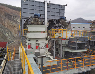
Process Flow Diagram Caustic Plant Power Plant Pulp Mill Black Liquor Green Liquor White Liquor. The Kraft Pulping and White Liquor •NaOH •Na2S Pulp Mill •Cooking •Washing Black Liquor Turpentine pulp. Raw Material. Structure of Wood Fibers Lumen P S1 S2 S3 Middle Lamella. Chemical Structure of Fibers O O HO OH O O HO OH O HO OH O O
WhatsAppGet PriceGet A Quote
side, the new sand is added, and the old sand replaced on the top of the new, thus retaining much of the active material to enable the resanded filter to become operational with the minimum re-ripening. This process (of replacing old sand on the top of the new) known as “throwing over” is carried out in strips.
WhatsAppGet PriceGet A Quote
In urban areas the slow sand filter simply occupies too much space. Therefore, rapid sand filtration has been developed and has become the most common type of filter for treating municipal water supplies. Typical filtration rate for rapid sand filter is 5 m/h, compared to 0.15 m/h in slow sand filtration. The area required for
WhatsAppGet PriceGet A Quote
I The proposed revised site plan incorporating the proposed washing plant and fines management system is shown in Figure 2.2, a schematic diagram of the washing I process is shown in Figure 2.3 and a flow diagram of the washing process is shown in I Figure 2.4. 2.2 RAW SAND RECOVERY AND STOCKPILING
WhatsAppGet PriceGet A Quote
Starting from silica sand with SiO2 content of minimum 98%, the plant allows to obtain a sodium silicate solution at 48°Bé density and ratio SiO2/Na2O in the range 1.6 ÷ 2.0. The production process is based on batch-wise operations. Standard plant capacity is 100 ton/day.
WhatsAppGet PriceGet A Quote
Client: Atlantic Pumps Ltd. UKUsed in the mining industry, a wash plant helps to clean dirty sand. In this 3D animated explainer video, you can see the diff...
WhatsAppGet PriceGet A Quote
All industries Aggregates Coal C&D Recycling Concrete Dairy Frac Sand Mining Waste Handling & Recycling. Solution. All solutions Bedding Management Crushing Dewatering Feeding Fines Recovery Manure Management Mixing/Blending Mobile Equipment Sampling Screening/Sizing Scrubbing Tailings & Water Management Washing & Classifying. Resource Type.
WhatsAppGet PriceGet A Quote
Basically, horticultural sand for plants serves one basic purpose. It improves soil drainage. This is critical for healthy plant growth. If soil is poorly drained, it becomes saturated. Roots that are deprived of oxygen soon die. Take a look at the following information and learn when to use horticultural sand.
WhatsAppGet PriceGet A Quote
Schematic diagram of sand filter setup Fig.5: Car wash waste water treatment plant with back washing. 3.3 Equipment and process design . There are different units in car wash .
WhatsAppGet PriceGet A Quote
storage and loading facilities. A process flow diagram for construction sand and gravel processing is presented in Figure 11.19.1-1. The following paragraphs describe the process in more detail. After being transported to the processing plant, the wet sand and gravel raw feed is stockpiled
WhatsAppGet PriceGet A Quote
Aggretek AWPWP3625 Portable Horizontal Wash Plant. Inventory Number: 607-6203-3625-2. View Details
WhatsAppGet PriceGet A Quote
Plan of the intakes The design of the suction pipe is as follows: Q = 0.17 m 3 /s V = 1.5 m/s The cross-sectional area of the suction pipe is A = Q / v = 0.17 / 1.5 = 0.11 m 2 .
WhatsAppGet PriceGet A Quote
Silica Sand Mining introduces. Foundry silica sand is the quartz as the main mineral composition, particle size of 0.020 mm to 3.350 mm refractory particles, according to the mining and processing methods of different can be divided into artificial silica sand and sand washing, sand washing, selection of natural silica sand such as sand (flotation).
WhatsAppGet PriceGet A Quote
Design of a sand and gravel washing plant Item Preview remove-circle Share or Embed This Item. Share to Twitter. Share to Facebook. Share to Reddit. No TOC. A few diagrams were printed with the print running to the very edge of the page and off the page. Addeddate 2009-12-17 18:44:59 Bookplateleaf 0005 Call number 750545
WhatsAppGet PriceGet A Quote
Sand Wash and Dry Facility Equipment and Process Flow Diagrams . Total H.P. 7070 Canadian Premium Sand. Frac Sand Processing Plant. Operating. Control. TPH. TPH. Process Equipment
Download scientific diagram | Flow diagram of a soil washing plant. from publication: Physical/chemical treatment of mercurycontaminated wastes from former chlorine-alkali electrolysis plants
WhatsAppGet PriceGet A Quote
• Sand becomes “fluidized”, and particles are flushed from the sand • Dirty backwash water is pumped into a settling pond, and either –Recycled back into plant, or –Di dDispose d • Backwashing can consume 1% to 5% of a plant’s production 21
WhatsAppGet PriceGet A Quote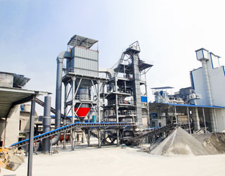
Sand Wash and Dry Facility Equipment and Process Flow Diagrams . Total H.P. 7070 Canadian Premium Sand. Frac Sand Processing Plant. Operating. Control. TPH. TPH. Process Equipment
Download scientific diagram | Flow diagram of a soil washing plant. from publication: Physical/chemical treatment of mercurycontaminated wastes from former chlorine-alkali electrolysis plants
WhatsAppGet PriceGet A Quote
Silica Sand Washing Plant Process With Diagram Sand production line includes sand production line and sand grinding production line. LDHB takes sand production line as an example to introduce equipment and process flow of sand production line.
WhatsAppGet PriceGet A Quote
Modular Wash Plants, such as the McLanahan UltraWASH, are assembled from containerized washing modules and produce up to five products, including three clean aggregate and two washed sand fractions. Additional modules can be added as needed to create a complete wet processing plant that is flexible enough to meet any production need.
WhatsAppGet PriceGet A Quote
26–6 (210-vi–NEH, October 1994) Chapter 26 Gradation Design of Sand and Gravel Filters Part 633 National Engineering Handbook Table 26–13 Data for designed filter band 26–29 Table 26–14 Design filter band data for example 26–6 soil 26–34 Table 26B–1 Selected standard aggregate gradations 26–41 Figures Figure 26–1 Grain size distribution curve for fine clay base soil 26–9
WhatsAppGet PriceGet A Quote
From sand classification, frac sand washing, scrubbing and dewatering, to water recycling and waste reuse, PHOENIX frac sand processing equipment helps optimize sand production to the correct standard for efficiency and profitability. Frac Sand is used when extracting subsurface minerals like oil, natural gas, or natural gas liquids.
WhatsAppGet PriceGet A Quote
CSE364 Handout doc. By Eric W. Course Code : 17CE5126 L-T-P structure : 3-0-2 Course Credits : 4 Course Coordinator Course Instructors. By Vijayan G Iyer. XIII-Water-C-Sewage Treatment-1 SEWAGE TREATMENT. By nasr rageh and sangar mohammad. Decentralised wastewater treatment methods for developing countries. By kajal kiran.
WhatsAppGet PriceGet A Quote
 WhatsAPP 24h online service


 24h Online Chat


